I made Cypherbot in response to robot kits. I think it's a question of where to put the money. It's silly making some stultifying, over-priced, "colour inside the lines" kit the gateway to meaningful experiments and experience. It's a combination of the grand and the humble. If a builder has any character, genuine imagination or desire then this is the venue for those qualities to shine.
Make it? Make it happen.
[My fab tools are a drill press, a cross-cut file, a Dremel, and a nibbler.]
I proceeded in stages, the entire project didn't come about all at once. It was a step-by-step process. That much should be evident from the pictures. The project's impetus was "National Robotics Week" and the afflatus was demonstrating to the clueless how to get something done (like anything else - you take a step, and then another, repeat.)
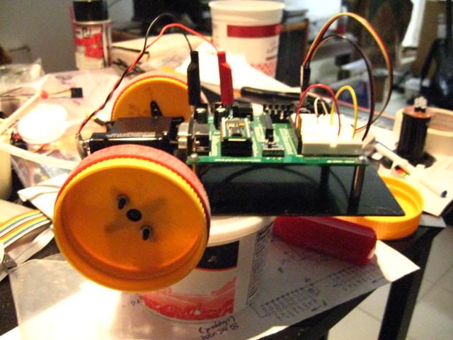
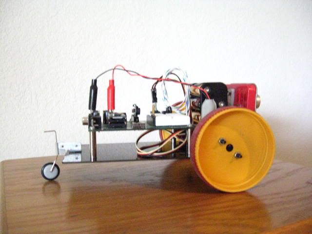
The base is a piece of plastic from my 'scrap bin'.
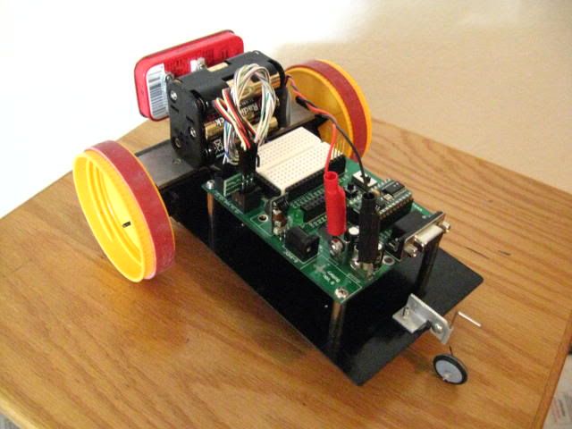
Cypherbot goes about with Parallax-Futaba continuous rotation servos firmly stuck onto the base with U-Glu strips. The servos get their signals from a Parallax ServoPal. The wheels were made from jar lids and I got the 'traction bands' from the blood bank.
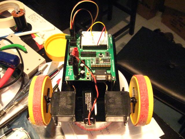
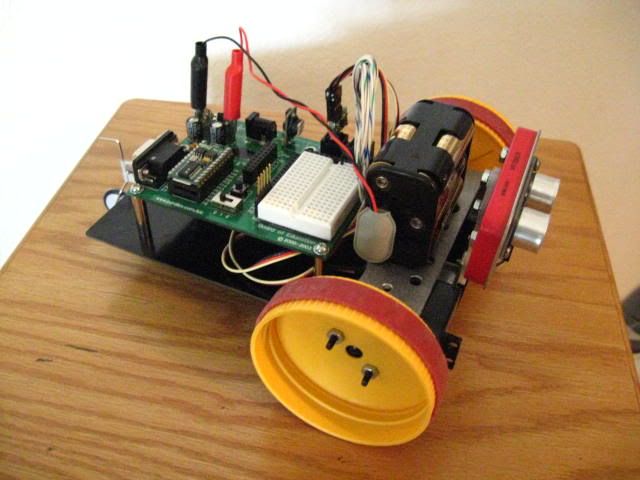
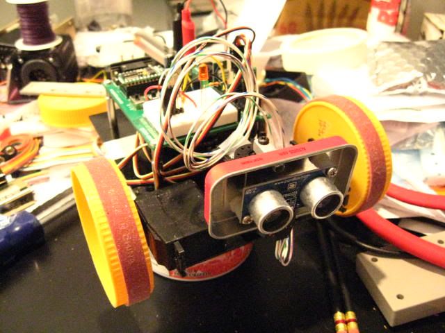
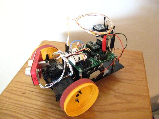
Its travelling around, trying to avoid thus and sundry, was interesting enough. I'd had the idea to run it remote controlled and the XBee modules now available from Parallax proved ideally suited to the task. They run from 3V and though I could've made do with a LM317L I got extravagant with a 7803SR (Mouser). I think these little switchers are the best. I fab'd a little board for the XBee, with a 3v-5v level shifter and the switcher.
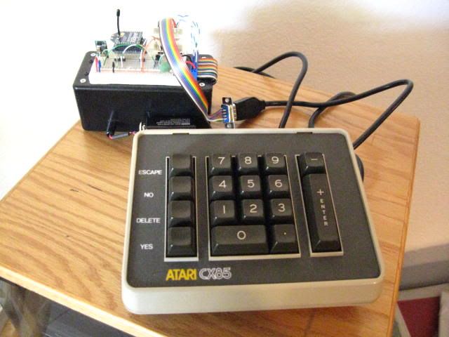
I need to situate an SX28 into the keyboard enclosure. The keyboard enclosure is held together with four self-tapping screws that go into plastic posts (not reinforced) which leaves me wanting to keep the battery external. So, for now, it's all separate pending further review. If you have to have everything perfect before you try anything then you'll likely do nothing; you have to start somewhere - perfect as you go along.
Here's the RC-a-Go-Go --
https://www.youtube.com/watch?v=U2HLGc8d95g
I make my cables on the long-side, admittedly - better too long (bundle it as necessary) than too short. A little more utility for use elsewhere.
(Both the RX and TX use the "out-of-the-box" 9600, 8N1 serial mode. No dicking around required.)
Update 082111 (About The Remote) --
Since the battery/power would necessarily be kept external, owing to my loathing of rechargeables (so-called) and all of the lying that goes with them, I decided to keep everything external.
I dispensed with the 7803SR and got 3V (3.15V, actually) for the XBee dropping voltage across 3 diodes coming off the 7805SR (an LED "on" indicator keeps that in good conduction.) Efficiency is a consideration, but it isn't everything, it feeds off the switcher anyway.
A schematic follows.
The grand solution takes the form of a "pod" attached underneath.

I went modular by placing the XBee on a pluggable card.


I leaded out the programming header and had room enough to stuff that into the battery compartment, no disassembly required for "firmware mods".


