This time of year, post-Christmas, I'd usually be going back and forth between the surplus supplier websites, loading carts, buying lots of stuff. The last years have seen some losses.
AEC closed this summer, the owners retired (50 years was enough, I guess), but there's an employee spin-off that's trying to get up to speed. BGMicro closed a couple of years ago.
Goldmine is still around. And Marlin P. Jones is still around (with reduced inventory - where have all the open-frame linears gone?).
Jameco is still operating, but they aren't surplus. DigiKey and Mouser are still, strong of course, because they primarily serve industry, but they don't discourage individuals.
Dan ofDan'shad retired, but after moving decided to continue from his new location. He has a small inventory - RF transistors and some interesting components.
I used to live in Santa Clara County. They had a few great surplus stores, peaking in the late 90s: the venerable Halted and a spin-off called Haltek, Weird Stuff Warehouse, Alltronics and Anchor Electronics. I guess I should not fail to mention Fry's (not the grocery). I think Anchor is still in business, but the merchandise was all new, basically. Weird Stuff didn't last long. Alltronics went all on-line and then a change in ownership. I think they're on their way out. Halted has gone out of business recently, too. All that shook out after I moved away from there.
What's going on? My speculation: fewer small businesses with inventory to dump, less excess inventory because of JIT, lack of hobbyist interest despite all the Arduino (they won't solder and the thought of transistors and resistors are figured a conspiracy) and -- amazon.
If you have an HC05 Bluetooth transceiver and you would like to change its name or password, or go from Mode0 ('slave') to Mode1 ('master'), then you will have to get it into AT mode.
Here are two wiring configurations. Which to use depends on whether you have a device with a pushbutton (ckt on the right) or not (ckt on the left).
Upload the following sketch.
[ It's Martyn Currey's, basically, but he used a single letter variable ('c', which I changed to 'ch') and I like 19200 bps for Serial. ]
#include <SoftwareSerial.h> SoftwareSerial BTserial(8, 9); // RX | TX const long baudRate = 38400; char ch =' '; boolean NL = true; void setup() { Serial.begin(19200); Serial.print("Sketch: "); Serial.println(__FILE__); Serial.print("Uploaded: "); Serial.println(__DATE__); Serial.println(" "); BTserial.begin(baudRate); Serial.print("BTserial started at "); Serial.println(baudRate); Serial.println(" "); } void loop() { // Read from the Bluetooth module and send to the Arduino Serial Monitor if (BTserial.available()) { ch = BTserial.read(); Serial.write(ch); } // Read from the Serial Monitor and send to the Bluetooth module if (Serial.available()) { ch = Serial.read(); BTserial.write(ch); // Echo the user input to the main window. The ">" character indicates the user entered text. if (NL) { Serial.print(">"); NL = false; } Serial.write(ch); if (ch == 10) { NL = true; } } }
The connection to +5V should be open at first. Assuming SerMon is ready, connect 5V. You are now in AT mode. (You may like to click Reset after Uploading.)
Type AT in the text to send window, then press ENTER. The HC05 should respond with 'OK'.
To check the version, type AT+VERSION?, then press ENTER. The HC05 should respond with '+VERSION (the number)'
To change the Name, type AT+NAME=the_name_you_like, then press ENTER. Confirm that by Sending AT+NAME?
I'm not absolutely certain that these configs get absolute full access to the complete AT everything. I found RNAME was ignored in one instance (not thoroughly investigated). It may be that Pin34 has something more (or RNAME didn't have a purpose in re. the version I tried that on).
My garage door opener is about 30 years old. The motor and mechanism are still good, but its receiver started going wobbly whenever it got hot outside. It's lost sensitivity to the remotes; the manual switch always works. Having no desire to troubleshoot the receiver (too much like work), I decided to make a replacement remote control system.
The remote and the stationary module are based on the ESP8266 (NodeMCU devboards). The ESP8266 (and ESP32) has "ESP-Now", a connectionless (wireless via the WiFi module) communication protocol, baked in. There are a few topologies to use; this application uses the simplest, 'one-way'. The remote, "sender", links only to its associated unit's MAC address. [I got a good education on all this compliments at randomnerdtutorials.]
I found good use for one of those "power-banks". It's one of the sort that require a minimum load (or they turn off). In the remote's build, this 'feature' is useful, beneficial. I do have to click it on, but I don't have to click it off: 15 seconds to take care of business, reasonable enough. I have it kaptoned on for now.
Even though the activation button I chose is tactile ("clicky"), I wanted a visual cue, too. I didn't mount and wire back an LED - I used the NodeMCU's on-board LED (D0). To see it, I nibbled out a recess and fashioned a window from bit of old CD jewel case. With expandability in mind, there's an unused pushbutton ready for future fun.
The stationary module is in a project box that sits on a DIN rail. Not much to see, just a NodeMCU and a 5V relay circuit (NPN, Common Emitter).Some might opt for a semiconductor, but relay contacts don't care about polarities or any of that.
It's powered by a 5V wall-pack with a USB-B Micro cable that plugs into the NodeMCU. Receiving the proper packet, it clicks a relay. The relay's contacts are wired in parallel with the local switch's terminals on the back of the motor box.
This is how it looked, with the USB-A connector --
I started working with this as a lead-up to my next project. They are still available, but cost twice as much as they did a couple of years ago. From what I can tell, playback quality is pretty good. Getting up to speed did not come without aggravation/s.
#1) Do not power the player from Arduino 5V, it's inadequate. It doesn't hurt anything but it causes problems with player volume and with the IDE.
I worked with two configurations: one is for programming and the other for use. For the "In Use" configuration, get a USB breakout and branch +5 from that to the player and to Arduino 5V (and Gnd). For the programming configuration, disconnect the breakout from its source and disconnect the Arduino 5V from it too.
When you start testing and all, it can get irksome going back and forth with it, but that's how it is. The current demand of the Catalex overtaxes Arduino 5V where that may dip low enough such that, basically, the IDE may not find an Arduino connected.
#2) At first I was trying to play tracks using the index scheme (CMD = 0x0f). And, supposedly, there's a way to set the volume (CMD = 0x06). The index works, having files in folders would be my preference, but my experience was that it was full volume regardless.
There's a command for playing a track at a specified volume (CMD = 0x22), which does work, but all of your tracks have to be on top (no folders / directories) to use it. But here, instead of playing by "index", basically the track's file name, it plays with reference to the file's position in the list.
Evidently, files should be named beginning with a number. I don't know whether there's a byte limitation. This also preserves track positions, the stack, if/as files are added.
Admittedly, I was getting more than a little fed-up and as I write this, having unwound some, I am wondering if a 0x06 (set vol) might work if issued immediately after a 0x0f (play track).
I've read about there being an "unsolicited message", FILE_END, but I haven't found anything spelling out exactly how to use it. A practical example was not included with the PDF. It's not needed for the project I have in my mind right now, but another would benefit from it.
I was a devoted C64 user from the time I bought one in '85 till the time I put it away in '96, on account of having moved house and gotten busier at work (time and circumstances) and so on. But, it was the greatest fun.
At one time I was experimenting, trying to develop a "wireless remote" joystick based on DTMF encoding/decoding and FM radio. Tone capture wasn't very snappy though.
Fast Forward 25 years to the present day. I got the idea of bringing back the C64 fun with some Arduino fun by utilizing the Esplora. With its integral accelerometer and handy buttons it seemed a natural as a controller platform. Combined with HC-05 and HC-06 Bluetooth modules and a Pro-Mini, a wireless game controller system was born.
The first step was to assess the Esplora playability by rigging the Esplora outputs to some open-collector transistors and those to the C64 joystick port. As that worked out acceptably, I worked out a couple of sketches that relied on SoftwareSerial with the Bluetooth modules.
The Esplora (transmitter) sets bits in a control byte based on the results of the accelerometer reads and a pushbutton, and transmits that, in a loop. The Pro-Mini (receiver) deconstructs the bits from the received control byte, applying those to output pins that control their respective transistors that interface with the C64 (via the Control Port, the CIA's pulled up inputs).
Most of all, I wanted to play Zaxxon (!) and Defender again. I have those on cartridges. I used Defender during development.
Trying out Zaxxon uncovered a dilemma. In Defender, joystick forward/back positioned the craft Up/Down, so I programmed the Esplora so that tilting up resulted a joystick forward. But that was incompatible with Zaxxon where a dive with the controller tilted up. To accommodate the difference I made an input to switch between the two modess. So, for Zaxxon tilting the Esplora down results a dive and up results a climb. The system works well, but could stand some tweaking vis-à-vis the accelerometer thresholds for forward/backward (up/down, dive/climb).
I found a composite to HDMI converter for around $20. The C64 looks great on the Big Screen.
All I've done so far has been with cartridges. I should pull out a disk drive and see how that goes. This should work with the Amiga, too (I could dig up Action Fighter).
Look on my "Where's the Code?" page for the transmitter (Controller64_TX03) and receiver (Controller64_RX02) sketches.
2018APR15
Began making a "bluetooth speaker". Using a BT receiver I found for sale on Groupon. It has RCA outputs and an 1/8 inch stereo jack for audio out as well as USB-B micro and USB-A jacks, too. The top wasn't difficult to remove, though a couple of screws are hidden. It doesn't have a battery, unlike the very small units you may find. From the description I thought it had a battery, being kind of heavy that way, but it has a weight placed inside without which it's very light. It worked well with the Grundig.
Wired out the BT pairing (red) and status (blue) LEDs as well as the main pushbutton, which serves as power and as a means of initializing pairing and re-establishing a BT connection, for relocation on the speaker's front panel.
I'm going to build an amplifier for it using the LM4871 (*2) which is designed for 5V applications. Not certain whether I'll have a panel-mounted pot because I won't know how much actual gain it has, how much control I'll need, till I build it. I am satisfied that the concept is sound, based on my test using my Archer amplifier.
2018APR21
Built up one experimental channel of the LM4871 amp on the old breadboard.
Decent volume with 20kΩ R_fdbk, but better with 33kΩ. No "0.39µF" for that input cap, but there's a range given for that (0µ1 to 0µ47) - so I used two 0µ1 in parallel [0µ2].
I didn't bother with the 'Shutdown' pull up, just tying pin 1 to GND.
2018APR29
Knocked out the speaker panel. Soft maple is a lot harder than soft pine. I don't have a scrolling saw or anything like that, and my single-speed jigsaw is only for super-hack, so I drilled holes around the speaker hole borders. Plan A was to remove the rest with a chisel, but chiseling with the grain wasn't working out so great and across it may as well have been rock (too much work). Plan B was rasping out the rest to fit. Cannot complete the job till the grille fabric, held up in post, is delivered. (It was "mis-sent", that's official USPS lingo, to another post office and has languished several days there already.)
There was a little chip-out, but a bit of grille cloth can hide a multitude of sins - assuming it ever gets here.
2018MAY11
Went with a sort of cross between "dead bug" and "manhattan" methods by cutting out 'islands' (instead of gluing down isolated pieces).
I didn't order any components, drawing strictly from accumulated inventory.
2018MAY13
Amplifier test 100% success, no "issues".
Continuing with the speaker panel, I glued some grille fabric but it has some sag; not terrible but anyway. Using some 'modern' synthetic fabric, black, which needs to be stretched out, somehow, but I couldn't think of a way to do that. Maybe there's a method on the web somewhere ("instructables"?).
Still haven't tested it all powered from the intended, 2-outlet USB "cube," - been running the BT-RX from that, with the amp from a separate linear power supply.
I found some brass fender washers to use as bezels around the front panel knob holes. I found some inserts coarse threaded external with machine thread internal, but decided to fix the speakers to the panel just using wood screws. The 'inserts' were a total pain in the hole.
2018MAY20
Completed the mounting of the speaker panel.
Cut, drilled and screwed in two struts. Gluing the struts would have been easier but would likely have made their removal destructive. I haven't altered the cabinet, I've really wanted to avoid anything like that - though I had to bore ever so slightly the 4 existing holes for the dial bezel for the LED/LCD bezel. I thought that I had 8 screws, but I only had 6, so I used hot-melt on the brackets between the struts and the panel.
[The seller wanted the cabinet sold or "it's going to Kutztown".]
Full USB Power success, both with the "cube" and the 5V rechargeable. I made a USB_A cable for Amp Power that plugs into the USB_A receptacle on the BT-RX ─ so only one full USB cable is needed (a USB_A to USB_Bmicro). Having the 5V rechargeable option makes it completely "wireless".
The sound is great, even better than I had anticipated.
I need to place the BT-RX and the amp board on a panel and commit to some finalized wiring. Everything is loose and alligator clips, rigged temporary.
Remaining on the to-do list are:
routing and mounting the Status LED and pushbutton to the cabinet front panel
building and testing the LED panel (threshold detector) circuit [Built, tested, but undocumented ─ as yet]
2018JUN13
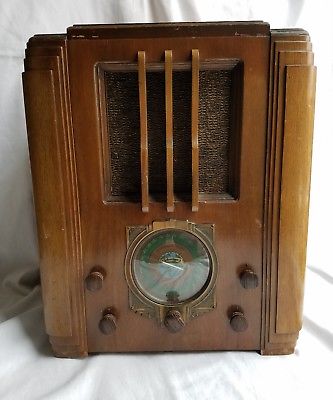
Of note - the cabinet is a Silvertone Model 1955 (c. 1936). Silvertone was the Sears store brand for their radios and, later, TVs and other home entertainment electronics. Here is a picture I found of one that's survived. They're 18 inches tall (2,160 cu. in.)
[When I bought it, there was only the cabinet for sale, the seller had no chassis for it.]
2018JUN14
Here's the first version of the threshold detector ─
The inputs are connected to the amplifier at the junction of Ri and Ci (see the amp schematic from 2018APR21). They're pre-biased at Vsupply / 2 (or 2.5V). The R1 pot is the threshold trip adjust. I will post a demo, "soon".
> > Have to add that that design is based on a circuit used in a Sharp/Optonica cassette that I once owned (a "peak" LED that went along with the VU meters). Really lazy "design", needs more work.
And I'm not liking how it's putting the first transistor circuit in the Amp/LM4871 feedback loop either.
I'll keep the diode-Or'ing on the input, to an op-amp buffer and then a comparator, the output of which will feed into a cap/hold-up circuit (better than) above.
2018JUN24
Here's the improved circuit. It has a nice fade-out, less blinky.
I added the 1M because it was susceptible to stray 60Hz otherwise. U1a is a unity gain buffer, U1b is a comparator, and the 10k pot sets the threshold.
2018JUL23
Yesterday was a long build session, but worth it. "Phase 1" is now Complete.
Here is the threshold detector / LED driver [TDLD] board --
Here is everything placed in the cabinet --
Yes, there's a lot of gaffer tape in place (for now). With gaffer tape you can hold down wires, and other stuff, without a firm commitment. The TDLD is there on the right where you can also see a boost converter (5 to 12V). I did the LED panel research with 12V and I wanted enough headroom for the op-amp, ergo implementing the boost mod (less than $5).
Here's the front --
I don't like the pushbutton (lower right), it doesn't look like it belongs. Its saving grace is requiring little pushing force. I dug up a much smaller pushbutton to replace that with. For now, pending work on "Phase 2", I'm using some hole-plugs for the holes on the left.
The speaker panel can be seen there despite the grille cloth, but only when seen through the camera.
Tomorrow I will upload a demo ("do not leave town!").
[Special Thanks to Dennis Zhang for lasering the 'dial plate'.]
Picked up this tuner-amp (c. 1968). I was drawn to its having a shortwave band. Note that the high frequencies are on the left.
Blew it out, cleaned it up a little - it's basically functional.
The previous owner tried rigging in a couple of RCA jacks to bypass the euro speaker connectors and it had no dial lights.
The back panel serves as in "interlock" of sorts. I removed the AC cord, drilling out the rivets. I may take a shot at fabricating a replacement back panel (from fiberboard or G10).
I found an ebay seller with the euro connectors and another with a DIN-to-RCA cable. The Phono and Tape inputs are via DIN jacks.
I replaced the dial lights. I must have been the first person to have done that. That's probably because doing so requires pulling the knobs and removing, extricating, the dial glass (a total PITA for dial lights). The lamp bases were practically frozen in their sockets. Curiously, they run from their own transformer secondary.
The left and right audio power amps are each powered from separate secondaries of their own. Those Grundig designers were generous with transformer windings. The AM and SW switches have an issue, I have to tap them to get a circuit engaged. I should go back in, those contacts may benefit from some DeoxIT in/on the contacts. [see Follow Up]
Tuning between FM stations results some noise like what you get from a noisy volume pot. I think this is the result of the receiver's lack of 'FM Muting'.
The Volume pot is not noisy - which is surprising. Likewise, neither Treble nor Bass pot exhibit any noise and Balance is clean, too.
"Aus Bayern, mit Liebe"
Follow-Up: Took the chassis out and sprayed some DeoxIT into the AM and SW select switches and it seems to good effect. They're sort of open at the back: spray and work 'em, wait, work 'em again, and repeat.
The back panel calls out "7V" lamps and, given my 6.3V #40's, I was bugged about the line measuring 6.8v(ac) - so I put a couple of diodes back-to-back in series, knocking that down to '6v'. [The two dial lamps and the one behind the tuning meter are in parallel.] As their brightness was excessive, garish, reducing v_lamp "to spec" this way made that nicer.
[Hadn't looked at the circuit board first time around, but upon going back in I noticed that the screws securing it to the chassis were soldered over.]
I was considering putting this in the front room as my 'daily driver', but it doesn't have a tape monitor loop.
Tuning SW stations requires extra patience because it doesn't have a fine tuning control. Nonetheless, I'd have been especially happy to have had this during the international broadcasting era. Sadly, there's not much to tune in anymore.
11FEB2018 - Good results with a couple of Bluetooth receiver configurations, connected with DIN to RCA adapter found on (where else?) ebay.
Chances are, if you're working with LabView then you have their USB-6008 DAQ. It's an I/O module. Its digital outputs are configured as "open drain". That's not uncommitted open drain, though - they're tied high, each via 4.7kΩ to its 5V. Not good for much at that rate and their "knowledge base" reveals a certain lack of electronics comprehension among users.
NI's suggested "fix ya" is a pull-up, but that doesn't hit it for the "ON = 5V" people or those who need capability greater than its paltry own unassisted. They may have reasons for doing this (keeping the electronically uneducated out of big trouble), but, clearly, the device is certainly limited.
There are better solutions, and this is mine: a high-side driver. It requires two components, a resistor and a PNP transistor.
All with the example build atop the 6008, the circuit diagram is shown beside the module in the following picture:
I used a 2N3906 because its rated collector current is 200mA and it's commonly available. The 750Ω value isn't super-critical (510Ω - 1kΩ will do).
It should be noted that users have to check the "Invert Line" box in the Config tab.
You don't have to limit yourself to the USB 200mA, get an external supply you have the power.